Power adapter is a type of external power supply that converts AC voltage into low-voltage DC or low-voltage AC output voltage. It has the characteristics of light weight, small size, and high conversion efficiency. It is widely used in small portable electronic equipment and household appliances, such as notebook computers and mobile phones. And other IT equipment, LCD flat-panel TV and other audio and video equipment, mobile phones and other telecommunications terminal equipment. The electrical safety of the power adapter device directly affects the electrical safety of the whole equipment, so it has a very important meaning.
The State Administration for Market Supervision and Administration announced that in the first quarter of 2018, the State Supervision and Spot Checks Report showed that a total of 70 batches of power adapter equipment produced by 65 power supply manufacturers were spot-checked, of which 12 batches did not meet the standards and the detection rate of unqualified products For 17.1%, the non-compliant items are mainly electrical insulation, creepage distance, electrical clearance, in-line equipment, heating requirements and electromagnetic compatibility items. Therefore, the author of this article combines the experience gained in the usual inspection work to describe and explain in detail the common safety substandard items of the power adapter for IT equipment.
 1 common substandard items
1.1 Marking and description
1) The sign or manual lacks the explanation of the meaning of the climate type and altitude symbol signs
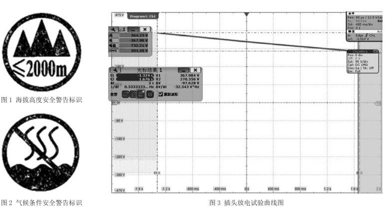
For equipment that is only suitable for use in areas below 2000m above sea level, “only for safe use in areas below 2000m above sea level” or a similar warning phrase should be marked on the obvious part of the equipment, or the mark shown in Figure 1 (when used alone) When marking, the meaning of the marking shall be explained in the manual).
For equipment that is only suitable for use in non-tropical climates, the obvious parts of the equipment should be marked with "only suitable for safe use in non-tropical climates" or a similar warning phrase, or the mark shown in Figure 2 (in When the mark is used alone, the meaning of the mark shall be explained in the manual).
In the usual inspections, it is seen that some devices only mark the symbols shown in Figure 1 and/or Figure 2 in the logo, but no explanation of the meaning of the logo is given in the specification. Once the user does not understand the meaning of the logo, it may lead to misuse and cause safety risks.
It is only applicable to products used at altitudes below 2000m. If used at altitudes above 2000m, there will be potential safety hazards (standards stipulate that products used at altitudes above 2000m have more stringent regulations on electrical clearance and other indicators); similarly, Products used only under non-tropical climate conditions, if used in areas under tropical climate conditions, will have safety hazards (products used under tropical climate conditions have more stringent regulations on wet treatment and other indicators).
2) Lack of fuse identification
In order to ensure that the fuse with the same parameters is replaced during the maintenance process, the standard stipulates that the rated current and other parameters shall be marked around each fuse in the product, on or around the fuse seat; it can also be represented by symbols such as F1, and a clear corresponding is provided in the manual Description.
In the usual tests, it is found that some products are not marked with relevant parameters, or the F1 symbol is marked on the products but there is no corresponding description in the manual.
1.2 Protection against electric shock and energy hazards
In order to ensure that there is no risk of electric shock at the external disconnection of the power grid due to the charge stored in the capacitor connected to the device, GB4943.1-2011 stipulates that the discharge time constant for type A pluggable equipment should not exceed 1s.
In the usual inspection, it is found that the discharge time constant of some products exceeds 1s, as shown in Figure 3.
In order to meet the corresponding electromagnetic compatibility and other regulations, power adapter products often install filter capacitors in the circuit. However, due to the unreasonable configuration of the capacitors and discharge resistors, the time constant exceeds the requirements of the standard.
The time constant refers to the product of equivalent capacitance (uF) and equivalent discharge resistance (MΩ). Since there may be multiple capacitors in the product, it is difficult to determine the equivalent capacitance and resistance value. The voltage attenuation can be measured at the external disconnection point. However, the voltage attenuation should be measured with an input impedance consisting of a 100MΩ±5MΩ resistor and an input circuit. The results are obtained by an instrument composed of capacitors with a capacity of 25pF or less in parallel.
1.3 Electrical insulation and electric strength
In order to judge whether the insulating material of the product is a hygroscopic material, GB4943.1-2011 stipulates that the equipment not used under tropical climate conditions should have a relative humidity of (93±3)% and an air temperature of 20~30℃. 48h of humidity treatment is carried out at any convenient temperature value (t±2)℃ that will not produce condensation; for equipment used in tropical climates, the air temperature is (40±2)℃ and the relative humidity is (93±3)% humidity treatment for 120h. After the damp treatment, conduct an electric strength test.
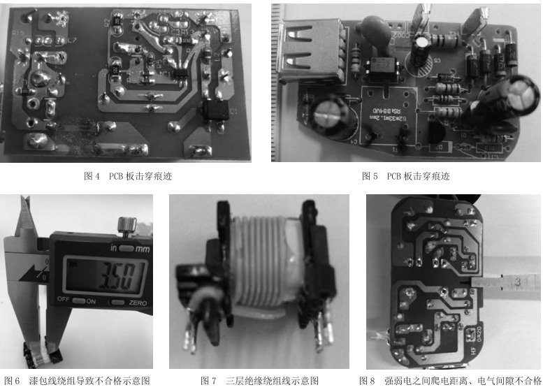
In the daily inspection, it is found that some products have breakdown phenomenon during the electric strength test. The breakdown marks are shown in Figure 4 and Figure 5. The reason for the breakdown phenomenon is that the printed circuit board (PCB board) is a hygroscopic sheet, which absorbs moisture under humid conditions, which causes the insulation performance to decline; and some are because the electrical gap between strong and weak currents is too small. There is a breakdown phenomenon.
1.4 Electrical clearance, creepage distance and insulation penetration distance The power adapter is small in size. When designing the circuit, the electrical clearance and creepage distance should be considered. In daily inspections, it is found that the insulated winding wire of some products uses enameled wire, which causes the creepage distance and electrical clearance between the primary pole and the secondary pole to not meet the standard requirements, as shown in Figure 6.
According to the standard, this problem can be solved by using a three-layer insulated winding wire that meets the requirements of Appendix U, as shown in Figure 7.
In addition, the electric gaps and creepage distances between strong electric charges and weak electric currents are often unqualified, as shown in Figure 8. The reason for the unqualified is that the technical personnel of the enterprise are not familiar with the meaning of electrical clearance, creepage distance and the corresponding detection methods, and it is difficult to design the safety structure of the product.
1.5 In-line equipment
For direct plug-in equipment, the power plug part should meet the requirements of GB1002 (the currently valid version is GB1002-2008 "Household and similar use single-phase plug and socket type, basic parameters and dimensions"), of which the most common single-phase two-pole The basic parameters and size requirements of the plug with rated current less than 6A are shown in Table 1. In addition, the distance between the plug pin and the edge should not be less than 6.5mm.
In the daily inspection, it is found that the plug pins of some in-line power adapters do not meet the standard, as shown in Figure 9. The reasons for non-conformity are mainly unfamiliar with the specific requirements of the standard and lax control during the incoming inspection.

1.6 Heating requirements
Thermoplastic parts directly installed with dangerous voltage components should be able to withstand abnormal heat and be checked for compliance according to the ball pressure test specified in GB/T5169.21-2006. The temperature value of the ball pressure test is (T-Tamb+Tma+15)℃±2℃, wrong! The reference source was not found.
Represents the temperature of a given component measured under the specified test conditions; error! The reference source was not found. Represents the ambient temperature during the test; error! The reference source was not found. Represents the highest ambient temperature allowed by the manufacturer's technical specifications or 35°C, whichever is higher. However, the thermoplastic parts supporting the primary circuit components should be tested at a temperature of at least 125°C.
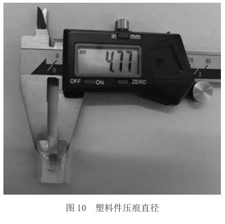
In daily inspections, it is found that some of the plastic parts supporting the pins of the power adapter have an indentation diameter greater than 2.0mm after the ball pressure test, which does not meet the requirements of GB/T5169.21-2006, as shown in Figure 10.

